BUILDING A ROUTER TABLE – PART NINE
Router table assembly
With the fence and guards completed it is time to drill any remaining holes in the tabletop, including those for the NVR switch, fit the top to the base, install the router in the insert plate, level it with the tabletop and install the fence, hold-downs etc.
Freehand guard
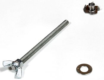
We changed the fixing method for the freehand guard in the light of experience. We replaced the system of 6mm bolts and wing nuts, with fittings made from 6mm studding, nuts, wing nuts and T-nut. This makes fitting and removing the guard very much easier.
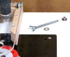
The home-made fixing is shown in Photo 46. It consists of a length of 6mm studding with a nut and wing nut locked together at one end. Locking the two together enables the rod to be screwed and unscrewed with the wing nut. 6mm pronged T-nuts are inserted in the underside of the tabletop to take the studding. A washer on each fixing completes the job.
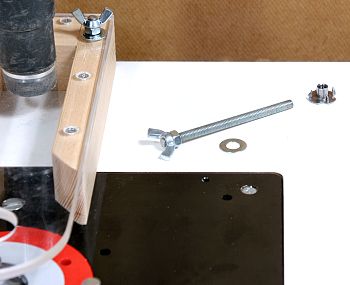
Photo 47 shows the guard with one of the new fixings in place and one on the tabletop.
Tips
1. Before cutting the studding with a small hacksaw, run two nuts on it, one either side of the cut. When you remove the nuts they will clean up any burr caused by your cutting.
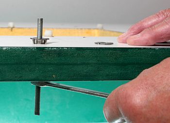
2. Do not try to hammer the T-nuts into the table. The best way of doing it is to drop a bolt or length of studding through the hole, screw it into the T-nut and put a washer and nut on the other end so that you can draw the T-nut into the tabletop by tightening the nut with a spanner. Photo 48 shows this operation.
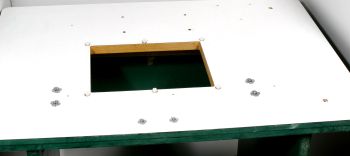
Photo 49 shows the upturned tabletop with the various fixing holes drilled in it. The two plain holes at the right-hand end of the top are for fitting the Incra jig. The six nylon levelling screws can also be seen around the insert plate cut-out.
Pressure guards
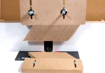
The vertical guard is held on 8mm studding. The studding projects forward from the wing nuts and can be hard on the knuckles. In use I push a piece of polythene tubing over the exposed ends of the studding, but this was left off in the photo for clarity.
The horizontal guard is held to the table with roofing bolts and wing nuts, dropped through plain holes drilled in the tabletop. The smooth bolt heads avoid having anything to catch your hands. Photo 50 shows the two pressure guards with their fixings.
Attaching the top
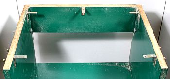
The top is attached to the base unit by means of five metal right-angle brackets, obtainable from the local ironmonger. If this looks flimsy to you fear not. I have been using this system for at least ten years with no problems at all. One of its advantages is that if you damage the top, or wish to make a different version, you can easily remove and replace it. Photo 51 shows the base unit with the brackets fixed in place.
The top is laid on the base unit and moved around until you are satisfied with its position in relation to the base and then simply secured with five screws.
Installing the router
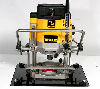
The router is attached to the insert plate as described in an earlier instalment. The corner snuggers are then fitted before the router is lowered into the table recess. Photo 52 shows the DW 625 router attached to the router plate with the corner snuggers fitted. It is standing in the table recess for photographic clarity. Note also that my DW 625 is fitted not only with the WoodRat PlungeBar but also the Router Raizer for precise cutter depth setting. Both of these are options that can be fitted later, if required.
The insert plate is then dropped into the table recess (drop the power cable through the hole first) and the corner snuggers partially tightened, to prevent much movement but at the same time allow the plate to rise on the levelling screws. The six levelling screws are then gently adjusted, with a straightedge across the tabletop to check for flushness. When the plate is exactly flush with the tabletop, the corner snuggers are then fully tightened into the corners of the recess.
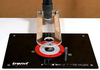
Photo 53 shows the insert plate in the tabletop along with the freehand guard and the lead-in pin supplied with the insert. The silver disc adjacent to the lead-in pin is a hole drilled for the winding handle of the Router Raizer. The disc blanks off the hole when the handle is not being used.
Note: The Trend insert plate was originally supplied with levelling screws but recent supplies of the plate do not include them and they do not seem to be available as an accessory. In their absence, make the table recess a whisker deeper than the plate and shim the plate with masking tape, coarse abrasive etc. until it is flush. Take pains to get this right.
Mitre fence
It will have been noticed that I have not incorporated a mitre fence slot in the tabletop. That is because I dislike mitre fences and do not use them. One reason is that cutting through the laminate into the MDF might cause the top to warp. A second is that if you use a mitre fence to guide the work at right-angles past the cutter e.g. for cutting tenons or scribing rails, you have to not only set the mitre fence so that the workpiece is exactly at right angles to the table fence but also ensure that the table fence is absolutely parallel with the mitre fence slot. If you do not use a mitre fence this second requirement does not arise.
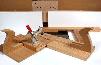
Since the vast majority of your mitre fence work would be for right-angled cuts, it is much easier to make various simple work-aids to guide your workpieces.
Photo 54 shows several of these work-aids. They will be described in more detail when we put the table through its paces.
NVR switch
An NVR switch is highly recommended, not only for safety reasons but also for the convenience it affords. It should be fitted in a position where it can be easily reached and, preferably, knocked ‘OFF’ with your leg or thigh if you get into difficulties.

