BUILDING A ROUTER TABLE – PART SEVEN
Making the fence
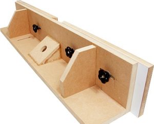
The fence is made of 18mm MDF and runs the length of the table. Two pieces of MDF are joined at right angles to form the main part, and two sliding cheeks, laminated both sides with Formica, provide an adjustable cutter aperture.
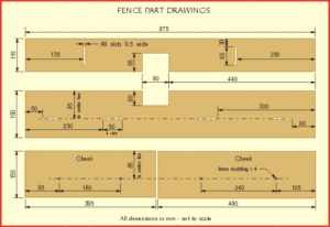
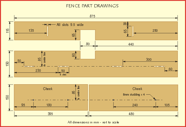
The dimensions are given in the diagram below. The sliding cheeks are 150mm tall to give a substantial vertical surface for jobs where the workpiece is run vertically past the cutter.
IMPORTANT: If you have set your insert plate to the left of centre as described in part 3, don’t forget to make the cutter aperture in your fence correspondingly off centre.
The dimensions above are for a table with the plate mounted about 80mm off centre.
Begin by cutting the two main components. We used a saw to rough cut, then trimmed them to exact size with a straight edge and the Wealden T8030B template trim cutter in the router.
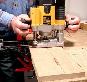
Photo 24 shows this operation.
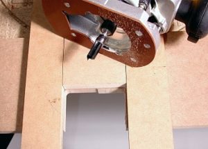
Next mark the positions of the cut-outs for the cutter aperture. Again we rough cut the openings with a saw and finished with straight edges and template trim cutter.
Photo 25 shows the partially completed cut in the vertical component.
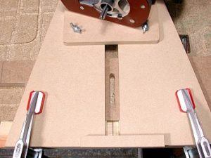
The two components now have to be slotted: the base for the fence-positioning bolts, and the face to allow the cheeks to slide. The slots in the base are cut with a 3/8in cutter to give comfortable clearance for the 8mm bolts. To guide the router I used my slotting/housing jig with a guide bush. The slot in the jig was made to be a snug fit for the bush.
Photo 26 shows a completed slot with the jig and the router.
The four horizontal slots in the face component, two for each sliding cheek, were cut with the side fence positioning the router. Since the material was MDF I used the DW 621 router, with its excellent dust extraction, but also wore a dust mask and eye protection.
Photo 27 shows one of the slots being cut.

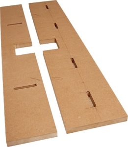
The two main fence components, ready for jointing at right angles, are shows in photo 28.
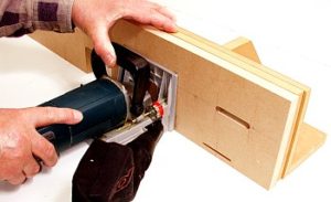
We jointed the two boards with biscuits. With 18mm material a good result can be obtained by removing the fence from the biscuit jointer and running it along a flat surface. For the face component we used the fence from my existing large table to hold the workpiece at right angles. Photo 29 shows this operation.
The two parts of the fence were glued and clamped with great attention paid to getting them exactly at right angles to each other. When the glue was dry, two bracing pieces were cut and glued in place, and a sort of ‘lean-to’ of MDF glued behind the cutter aperture to provide a dust extraction take-off. The sloping piece had a hole cut in it, with my small-circle cutter, to take the extractor hose connector. The next job was to make the two sliding cheeks. As before they were cut and trimmed to exact size, then laminated on both sides with Formica. We let the contact adhesive dry overnight then trimmed the laminate with a short flush-trimming cutter. The thickness of the MDF made it possible to laminate both sides before trimming, with adequate space for the cutter bearing and Allen screw between the layers. Photo 30 shows this operation in progress.
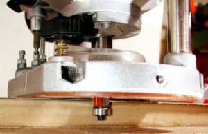
Finally we fitted lengths of 8mm studding into the backs of the cheeks to lock them in position when set to the required width. We drilled 7.5mm holes for the 8mm studding, put a little glue in the holes, and screwed the studding in with the old trick of locking two nuts on one end of it and driving it with a spanner. Photo 31 shows one of the pieces of studding being driven into the back of the cheek. WARNING: DO NOT DRILL TOO DEEP. 6MM IS ENOUGH TO LOCATE AND HOLD THE STUDDING.
Photo 32 shows a rear view of the completed fence. The various slots, sliding cheeks, bracing pieces and dust extraction take-off can all be clearly seen. The black female lobe nuts holding the cheeks are available from the Wealden online store in the accessories section. With the fence complete, it now remains to make the guards and hold-downs, drill the table top for various fixing points, and set the whole thing up.
