BUILDING A ROUTER TABLE – PART SIX
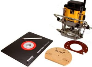
Fitting the router to the insert plate
The insert plate used for this table is the US-made Trend phenolic plate, for which the table top was recessed in a previous section. The present task is to drill the plate with the appropriate fixing holes for the intended router.
Our router is the De Walt DW 625 which, in common with a number of other models, has three 6mm tapped holes in the base for attaching to a table. These holes are placed in the standard Elu/ De Walt/Trend positions, so a plate drilled to take the 625 will also take a number of other models.
The plate has a number of concentric rings moulded in the underside. These are to help you mount your router centred on the insert plate aperture. The instructions advise you to remove the sole plate from your router, centre it on the moulded rings, tape and clamp it to the plate and use it as a template to drill the router fixing holes. This works, but I have an alternative method which I prefer.
Photo 17 shows the essentials.
Step 1
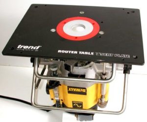
The plate has reducing rings to cater for different diameter cutters. The smallest aperture is about 31mm. The DW 625 has a 30mm guide bush as standard. Put this in your router. You can make it a tighter fit in the 31mm aperture by wrapping a piece of masking tape around the flange.
Photo18 shows the router fitted with the 30mm guide bush with masking tape to make it a snug fit in the insert-plate aperture.
Now stand the insert plate face down on two battens to raise it clear of the bench surface and place the router on it with the guide bush in the aperture. This locates the router dead centre with regard to the cutter aperture.
Step 2
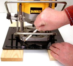
Rotate the router until it is positioned to your satisfaction i.e. with the controls where you want them. Make sure that the router is in the correct position for when it is inverted in the table, and that the plate is right way round i.e. with the lead-in pin holes to the right when installed. When you are satisfied, draw round the router base with one of those pens or pencils that write on anything. Lift the router off the insert plate.
Photo 19 shows the router, aligned in the insert plate, with the outline of the base being drawn around it.
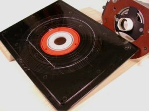
Photo 20 shows the insert plate with the outline of the router base, in the desired alignment, drawn round it.
Step 3
If you have previously made an MDF pattern of your router base attach it to the pencilled outline on the insert plate with double-sided tape. If you have not got a base pattern remove the sole plate from the router and tape this to the drawn outline.
Use a fair amount of the tape to ensure that the plate does not move while you are drilling it. (If you are uncertain of whether your tape will hold fast, work on the smooth upper surface of the plate).
Now use the pattern or sole plate as a template for drilling the fixing holes.
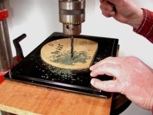
Photo 21 shows the MDF base pattern taped to the drawn outline on the insert plate being used as a template to drill the fixing holes. The router sole plate would be used in exactly the same way.
With the fixing holes drilled, remove the base pattern and countersink the holes from the upper side of the plate.
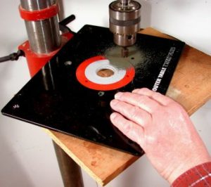
Photo 22 shows this operation.
The phenolic plastic from which these commercial plates are made is hard so a good sharp drill bit and countersink bit, plus a spray of silicone or PTFE, will make the drilling and countersinking easier. Drill in easy stages and withdraw the bit to cool between stages.
That’s all there is to it. You now have three countersunk holes in your insert plate in exactly the right places to position your router dead centre to the cutter aperture. All you now need are the appropriate countersunk machine screws, which, for the DW 625 are 6mm.

Photo 23 shows the router attached to the insert plate with the three 6mm countersunk screws.
